Building automation and smaller plant systems often need only a few additional physical inputs or outputs. The requirement may be simple: eight dry contacts, a group of relay outputs or several universal signals. Adding another large controller only to gain a handful of I/O points can be excessive. Siemens EM1.8D, EM1.8R and EM1.8U modules are interesting because they provide compact I/O extension with Modbus RTU communication.
For the system integrator, however, hardware alone is only half the story. Commissioning and service must also be efficient. On site, the engineer needs to know which module is present, which address it uses, whether communication is stable and whether the physical signal maps correctly to data. That is why NODVIA Field includes a dedicated Siemens EM1 Tool.
What are EM1.8D, EM1.8R and EM1.8U?
Siemens EM1 is a family of I/O extension modules within Desigo Essentials. The three variants have a straightforward purpose:
| Model | Core function | Typical use |
|---|---|---|
| EM1.8D | 8 digital inputs | dry contacts, status signals, switches, alarm contacts |
| EM1.8R | 8 relay outputs | on/off device control, signalling, relay control |
| EM1.8U | 8 universal I/O | analogue and digital signals, sensors and flexible I/O applications |
EM1.8U is primarily about flexibility. Siemens documentation supports multiple analogue and digital channel configurations, which is useful when each point should not be locked to one signal type. For the designer this can reduce the number of different module types; for the service engineer it makes understanding each channel configuration especially important.
Why Modbus RTU matters
Modbus is one of the most widely implemented industrial communication protocols. The official specification describes a request/reply application-layer protocol built around function codes. Serial implementations are commonly carried over RS-485. Its strength is not novelty but simplicity, documentation and broad support across controllers, gateways and service tools.
Siemens publishes the EM1 register map and supported function codes. The documentation covers digital-input reading, coil reading/writing and holding-register reading/writing. For integrators this is useful because the module can be connected to systems that support the documented Modbus interface, subject to the project design and manufacturer requirements.
Where EM1 can be cost-effective
“Cost-effective” always depends on project pricing and alternatives. The EM1 concept is nevertheless attractive when only a modest number of extra I/O points is required and Modbus RTU fits the architecture. In such cases a compact extension module can be more economical than another large controller or a more complex remote-I/O system.
Typical cases include smaller HVAC equipment requiring extra status points, relay commands or analogue signals; extensions where physical I/O is remote from the main controller but RS-485 is easy to provide; and collection of contact signals from equipment without its own communication interface.
For customers in Slovenia, FENIKS PRO d.o.o. is one possible supplier. Current availability, price and suitability for the specific project should be confirmed before ordering.
Why a generic Modbus browser is not always enough
A generic Modbus scanner is excellent when the register map, Unit ID, baud rate, parity and data type are already known. Field service often starts one step earlier. The technician may only know that several modules are connected to an RS-485 bus. Addresses may be unclear, a module may have been replaced or site documentation may be out of date.
In that situation, manually testing combinations consumes time. A device-specific tool can therefore provide more value than a generic register browser: discover the module first, then present its identity and I/O in a meaningful interface.
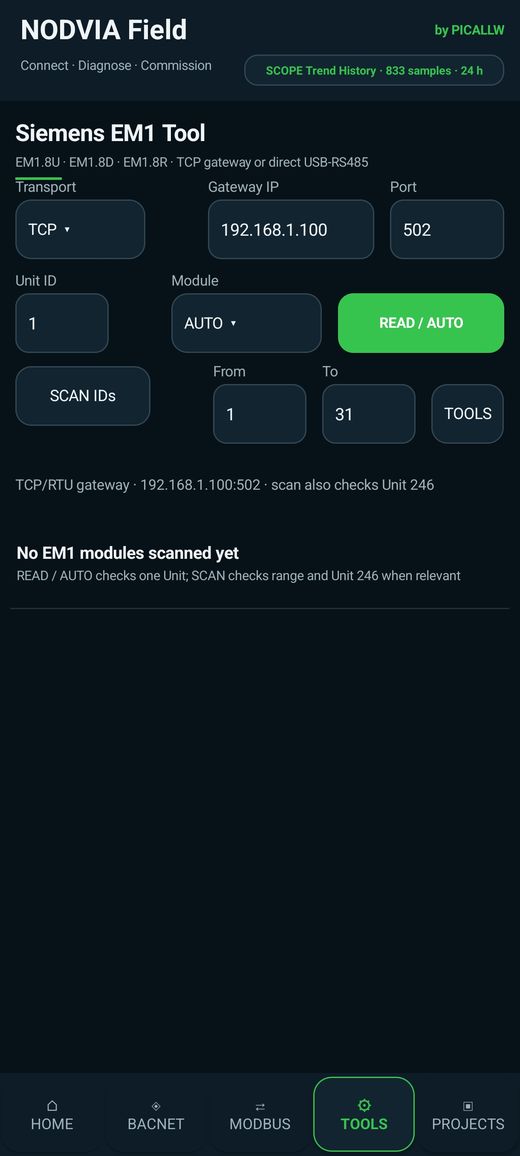
NODVIA Field EM1 Tool
NODVIA Field is positioned as the Swiss Army knife for building automation engineers. Alongside BACnet, Modbus, KNX, Climatix, M-Bus and network tools, EM1 gets a dedicated service view.
The basic workflow is straightforward:
- connect the phone through the appropriate USB/serial interface or selected Modbus path;
- start EM1 module discovery;
- let the tool scan Unit IDs and identify present modules;
- select a discovered module and inspect its I/O information;
- verify communication parameters and use supported settings where appropriate;
- retain the result in the project or continue with integration.
Dedicated discovery means the user starts with the physical device, not with register 40001. That is much closer to how field service is actually performed.
Commissioning: from bus to signal
Commissioning should be systematic. Check the physical layer first: power, RS-485 polarity and topology, termination, shielding and duplicate addresses. Only then move to registers or application-level troubleshooting.
Once communication is stable, verify individual channels. For a digital input, change the physical contact and confirm that the value follows. Relay outputs require much more care because a manual write can energise real equipment. Universal channels require both the value and signal configuration/range to be checked.
Common first-commissioning errors
Many Modbus I/O problems are surprisingly basic. One is duplicate addressing: two modules respond to the same Unit ID and communication becomes unstable or unpredictable. Another is incorrect baud rate or parity. A third is reversed RS-485 polarity or poor bus topology. A fourth is the register offset problem, where documentation numbers a register from 1 while the tool displays it from 0. A fifth is data interpretation: the correct register is read but shown using the wrong type or scaling.
A device-specific tool can prevent some of these mistakes, but it cannot repair a poor physical installation. Good commissioning is always a combination of electrical inspection, protocol diagnostics and application understanding. NODVIA Field is most useful when it supports that systematic process rather than encouraging random register changes.
Which EM1 should you choose?
If the requirement is simply binary status inputs, EM1.8D is the obvious candidate. If eight straightforward relay commands are needed, EM1.8R may fit. When signals are mixed or project requirements may change, EM1.8U provides greater flexibility. The decision should not be based on I/O count alone: electrical characteristics, load ratings, sensor types, power supply, mounting, environmental limits and the communication topology all need to be checked in the official data sheet.
Lifecycle matters too. A cheap module that nobody can diagnose later may become an expensive service problem. A well-documented Modbus module combined with a practical field tool has additional value because the integration is repeatable and the service team can understand the device faster.
Integration into the wider system
EM1 is often only the lowest layer. Above it may be a PLC, BMS controller, gateway or NODVIA Connect. It is useful to separate three levels: the physical signal, the Modbus representation and the supervisory data point. If a digital input changes correctly in EM1 Tool but appears incorrectly in SCADA, the fault is probably higher in the chain. If it does not change at the module level, wiring or channel configuration should be checked first.
This layered approach prevents random changes at multiple levels at once. A field tool helps isolate whether the problem is the device, the protocol or the supervisory integration.
Automatic discovery does not replace documentation
NODVIA Field is designed to reduce time to useful information, not to hide the technical foundation. Official Siemens documentation remains the reference for allowed configurations, registers, electrical characteristics and commissioning procedures. A dedicated mobile tool is most useful when used together with good documentation.
That is why primary Siemens sources are linked below. If a register, behaviour or allowed configuration differs from expectations, the current manufacturer documentation takes precedence over any third-party summary.
EM1 as an example of the NODVIA Field philosophy
The EM1 Tool illustrates the wider NODVIA Field philosophy. The app is not intended to be only a collection of generic protocol screens. Where useful, it adds protocol-specific and device-specific tools that remove unnecessary steps. Climatix SCOPE MINI is another example.
This matters during commissioning: Connect first, Diagnose second, Commission third. Automatic discovery and a device-aware interface reduce the chance of using the wrong register, wrong address or an unnecessary write.
Conclusion
Siemens EM1.8D, EM1.8R and EM1.8U combine a practical amount of I/O with widely supported Modbus RTU. For many small and medium tasks they can be a cost-effective extension, particularly where the existing architecture already supports RS-485/Modbus.
The NODVIA Field EM1 Tool adds the other half of the story: faster field discovery and service. Instead of beginning with manual guessing of addresses and registers, the technician begins with the device. That is a small workflow change that can make a meaningful difference on site.